Group 1 Dedeoglu Behringer Virkki
Group members
Documentation page: Lasercutting
To understand how the Epilog Fusion 75 W CO2 laser behaves and to find good cutting and engraving settings, we ran a series of test cuts and measurements.
Safety
Before working with the Laser-cutter we got a quick introduction to the safety measurments. The training included Recognizing fire hazards and knowing emergency procedures, including the locations of fire extinguishers and fire blankets; handling materials safely to minimize exposure to toxic fumes and following guidelines for machine maintenance and safe operation.
Whenever using the machine, the responsible person needs to watch the machine all the time. Watch means, their eyes have to look at the Laserpointer cutting, because it can take only a few seconds for a fire to become a disaster. In case of increased smoke formation or fire, you should stop the job, open the lid a tiny bit and take out the burning part or cover it with a fire blanket.
Setup
| Step | Image | Description |
|---|---|---|
| 1 | 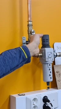 |
Turn on the the air filter |
| 2 |  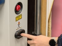 |
Turn on the laser cutter |
| 3 | 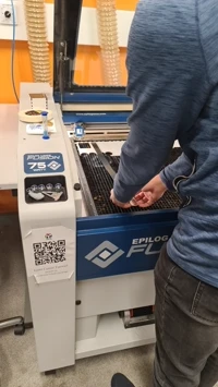 |
Place and i.a. measure the material, make sure to align it properly to the edges or pin the material |
| 4.1 | 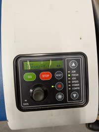 |
Focus the Laser, i.e. adjust it to the material's thickness |
| 4.2 | 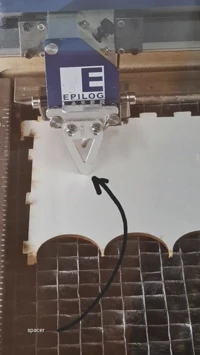 |
Adjust the height of the laser in a way that the metal pin barely touches the material |
| 5 | No picture available: go to Jog and then move the pointer to desired starting point. Save by pressing the Joystick. | Set the starting point |
| 6 | tutorial from 2:45 onwards | Open the .pdf file of the model and press print |
| 7 | 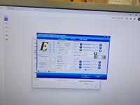 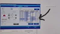 |
Select your Material, the DPI, speed, etc. in the advanced settings and press print |
| 8 | No picture available: go to job and choose your file. Start by pressing "Go". | After the Job is transmitted to the laser cutter, start it manually |
After the job finishes, you have to wait 1 minute before opening the lid, because there might be some toxic gases right after.
Focus
We tested cutting in and out of focus by changing the z-height of the bed.
- In focus: The cut line is sharp, narrow and clean.
- Out of focus: The beam spreads, producing a wider and less precise cut, sometimes not cutting through completely.
This showed how important correct focusing is for clean edges and consistent kerf.
To examine the effect of the focus distance on cutting quality, we used the provided focus test piece with several small shapes cut at different Z-axis offsets.
The test included positions of 0.00 mm (in focus), +1.00 mm, +4.00 mm, –1.00 mm, and –4.00 mm from the correct focal point.
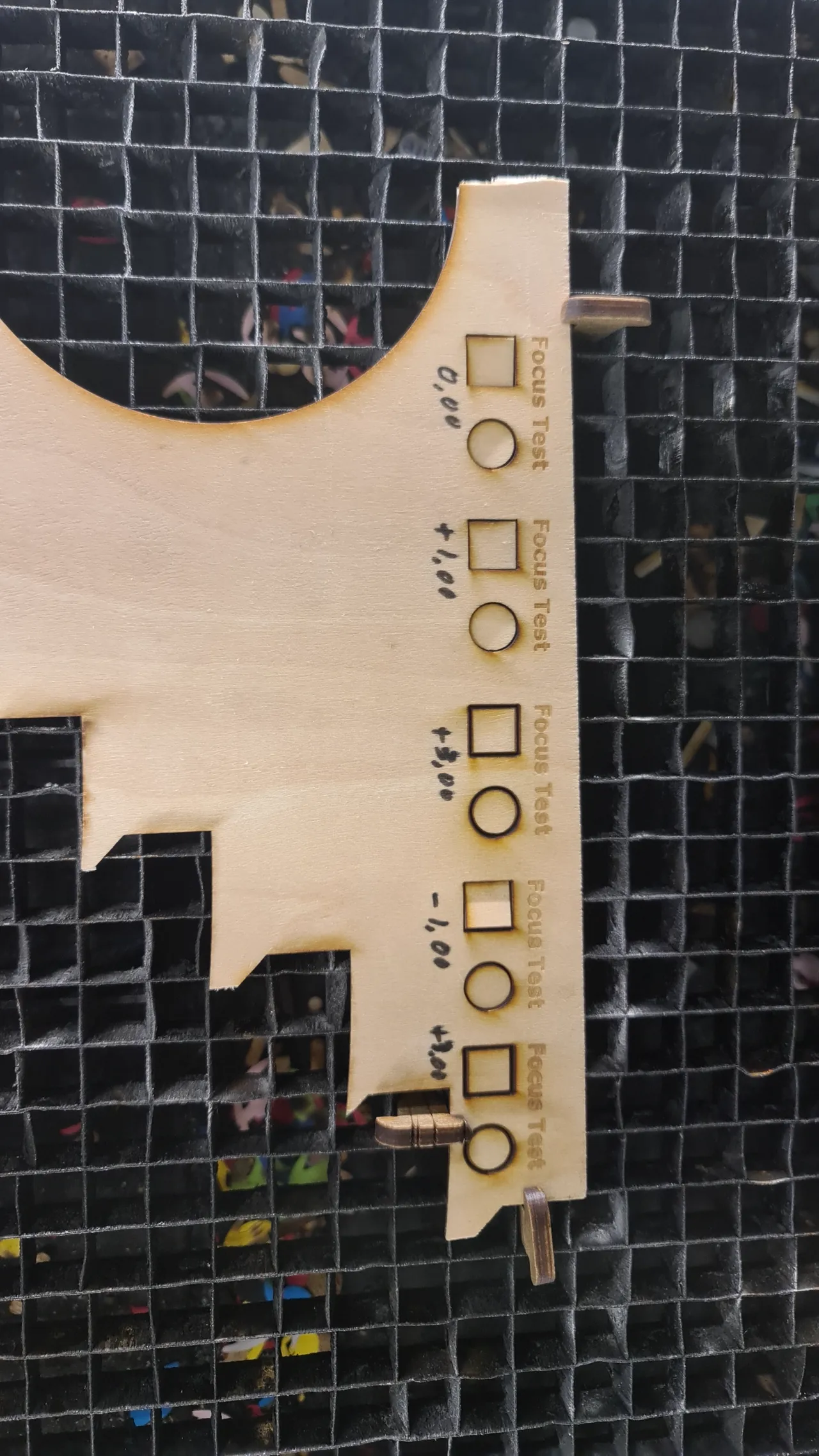 note that the first +3.00 has to be a +4.00 and the last +3.00 has to be a -4.00
Results:
• 0.00 mm (in focus): Clean, sharp cut with minimal burn marks.
• +1.00 mm / –1.00 mm: Slightly wider cut lines and less consistent engraving depth.
• +3.00 mm / –3.00 mm: Noticeably unfocused beam - edges were wide, burned and did not cut through completely.
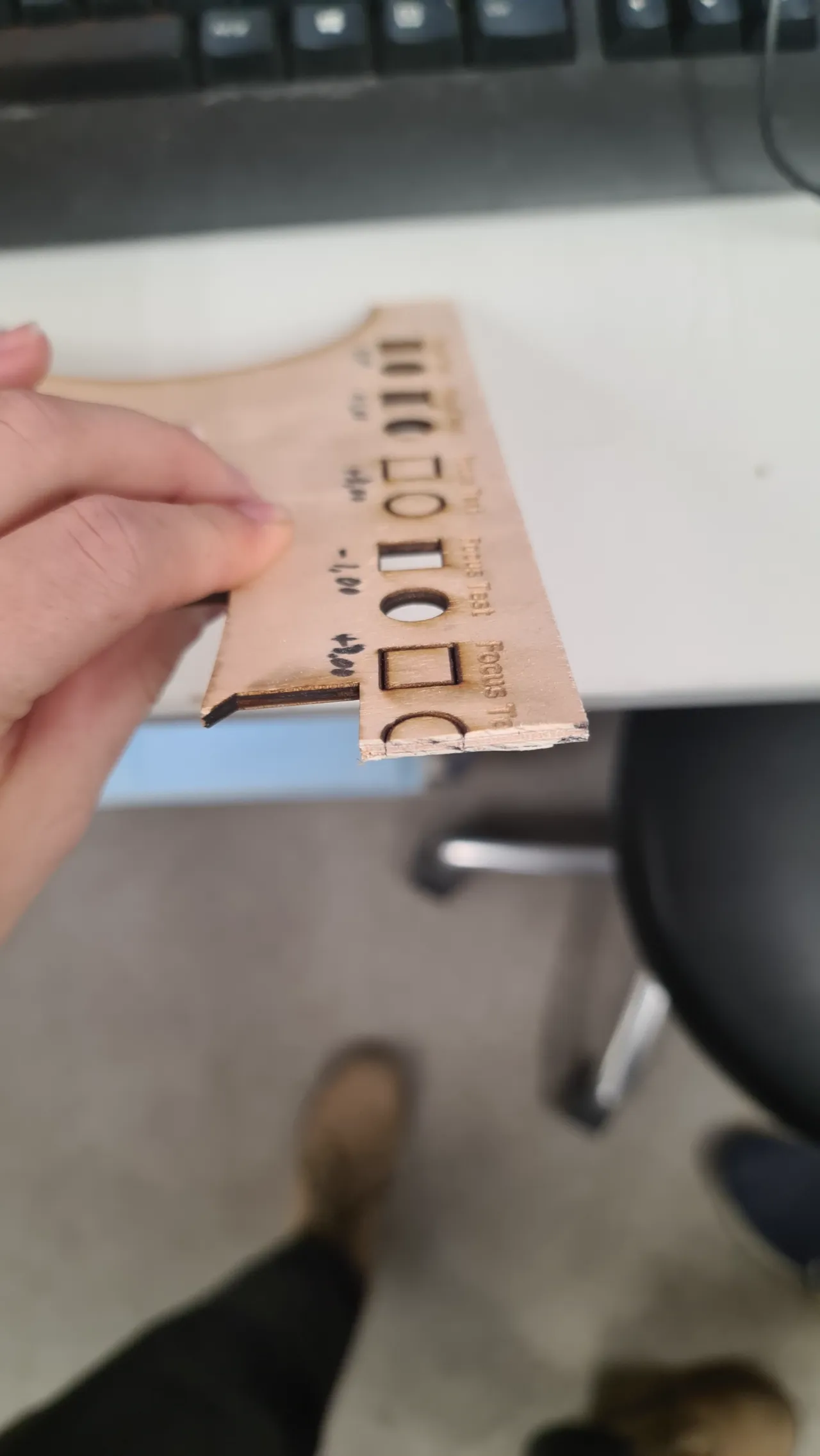 This clearly showed that maintaining the correct focus distance is essential for achieving clean and precise laser cuts.
Kerf
To measure the laser kerf, we used the small frame test piece with a nominal inner dimension of 50 mm. After cutting it with the Epilog Fusion 75 W CO2 laser, we measured the actual inner size using a caliper. The total material loss over 10 cuts was about 0.8 mm, which results in:
Kerf = 0.8 ÷ 10 = 0.08 mm
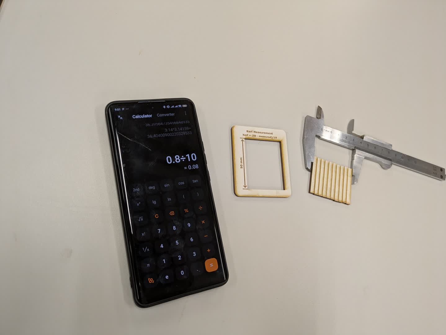
That means the laser removes approximately 0.08 mm of material per cut line (≈ 0.04 mm per side). This value is useful when designing press-fit joints or precision parts.
Press-Fit Test
To find the optimal press-fit clearance, we used a test piece with slots that varied from +0.10 mm to –0.35 mm in 0.05 mm steps. This means each slot was slightly wider or narrower than the nominal material thickness (3 mm plywood). After cutting and testing each slot with matching tabs, we observed the following results:
| Offset (mm) | Fit Result |
|---|---|
| +0.10 | Very loose fit |
| 0.00 | Good fit, a bit easy |
| –0.15 / –0.20 | Perfect press fit - tight but still insertable by hand |
| –0.25 | Very tight, hard to insert |
| –0.30 / –0.35 | Too tight, risk of breaking the material |
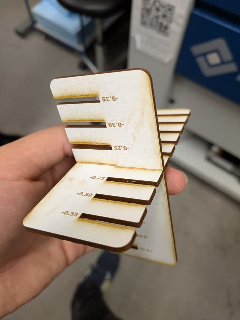
From this test, the ideal joint clearance for 3 mm plywood on our laser cutter is between –0.15 mm and –0.20 mm, considering a measured kerf of 0.08 mm.
DPI test
The goal of this test was to evaluate how engraving resolution (DPI) affects the engraving quality, depth and contrast on wood. Observations
300 DPI: Engraving appears light and slightly grainy. The wood texture remains visible through the engraved areas. Small text is legible but lacks sharpness and contrast.
600 DPI: Noticeably darker and more consistent engraving. Text is sharper and easier to read. Surface texture appears smoother and more uniform. A good balance between detail quality and engraving time.
1200 DPI: Very dark engraving with deeper ablation. Edges of engraved areas show slight overburn and minor smoke staining.
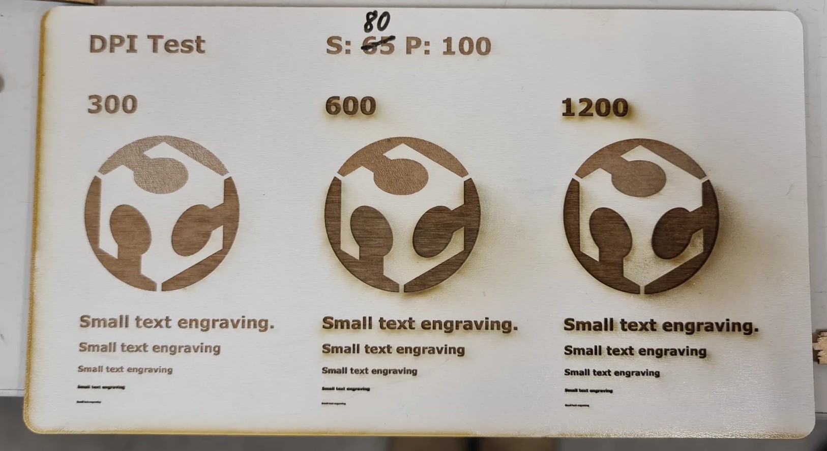
This DPI test shows how resolution directly affects energy density during engraving. While power and speed remain constant, increasing DPI effectively multiplies the number of laser firings per inch: resulting in darker, deeper engravings and longer processing times. For most applications on wood, 600 DPI provides a visually sharp result without excessive burning or time consumption.
Power and Speed (Engraving Test)
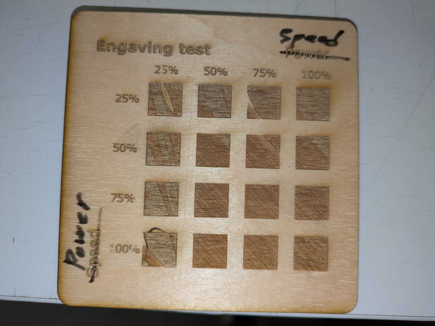
To understand how power and speed affect engraving depth and contrast, we ran a matrix test on plywood.
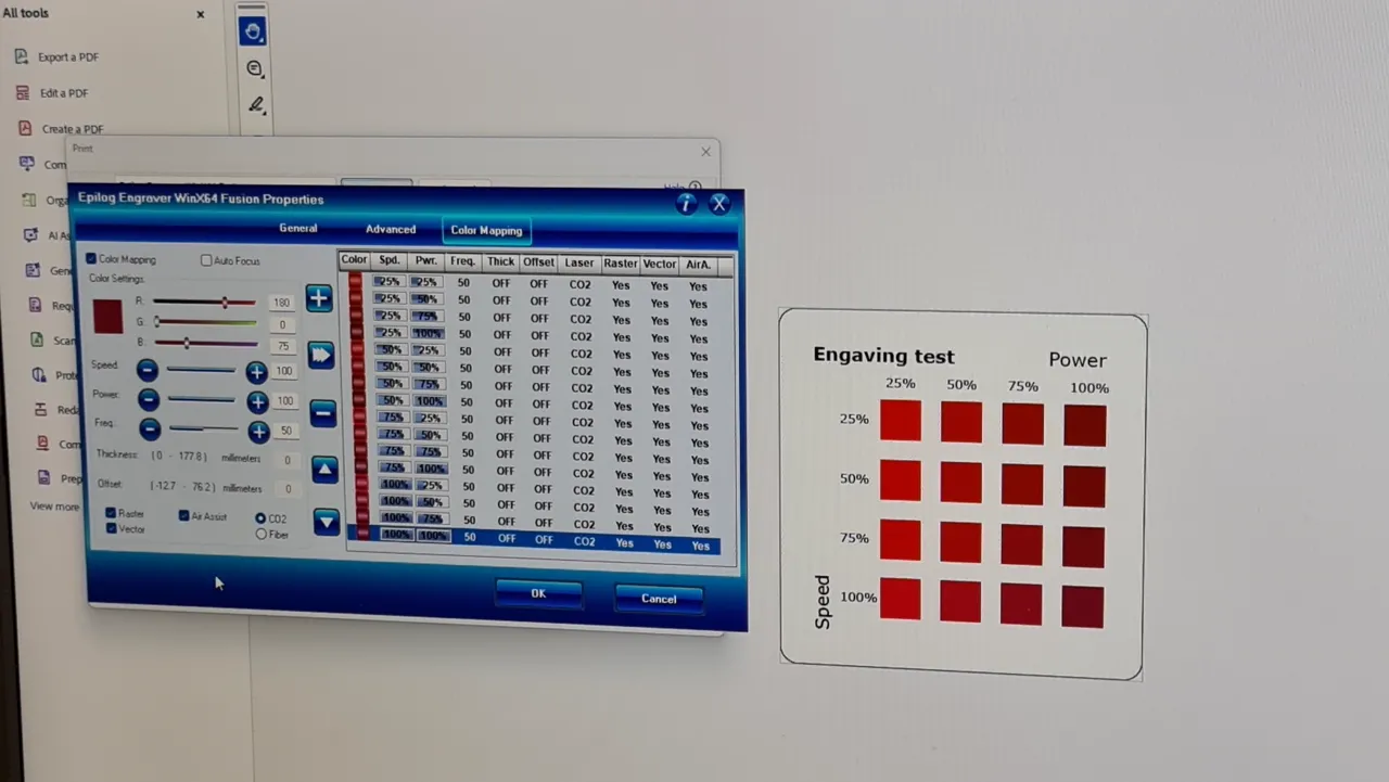
The horizontal axis represents speed (from 25 % to 100 %) and the vertical axis represents power (from 25 % to 100 %).
-
High power / low speed (bottom left): Deep engraving, dark surface, and some charring.
-
Low power / high speed (top right): Very light engraving, sometimes barely visible.
-
Middle range (50 %–75 %): Clean and readable engravings with minimal burn marks.
From this test, we found that for this plywood, around 60 % power and 70 % speed gives a good balance between contrast and surface quality.