Group Nguyen Krajewski others
Group members
- Khai Nguyen
- Hoang Bach Nguyen
- Ly Thai Hoa
- Miglio Krajewski
1. Microcontroller Circuit Board Observation
Equipment used
- Tektronix MSO 2002B Mixed Signal Oscilloscope
- 2*Tek 30V Oscilloscope probe test hooks
- PCB
- USB-A to USB-C connector
- Laptop
- Neopixel
- Servomotor
Test set-up
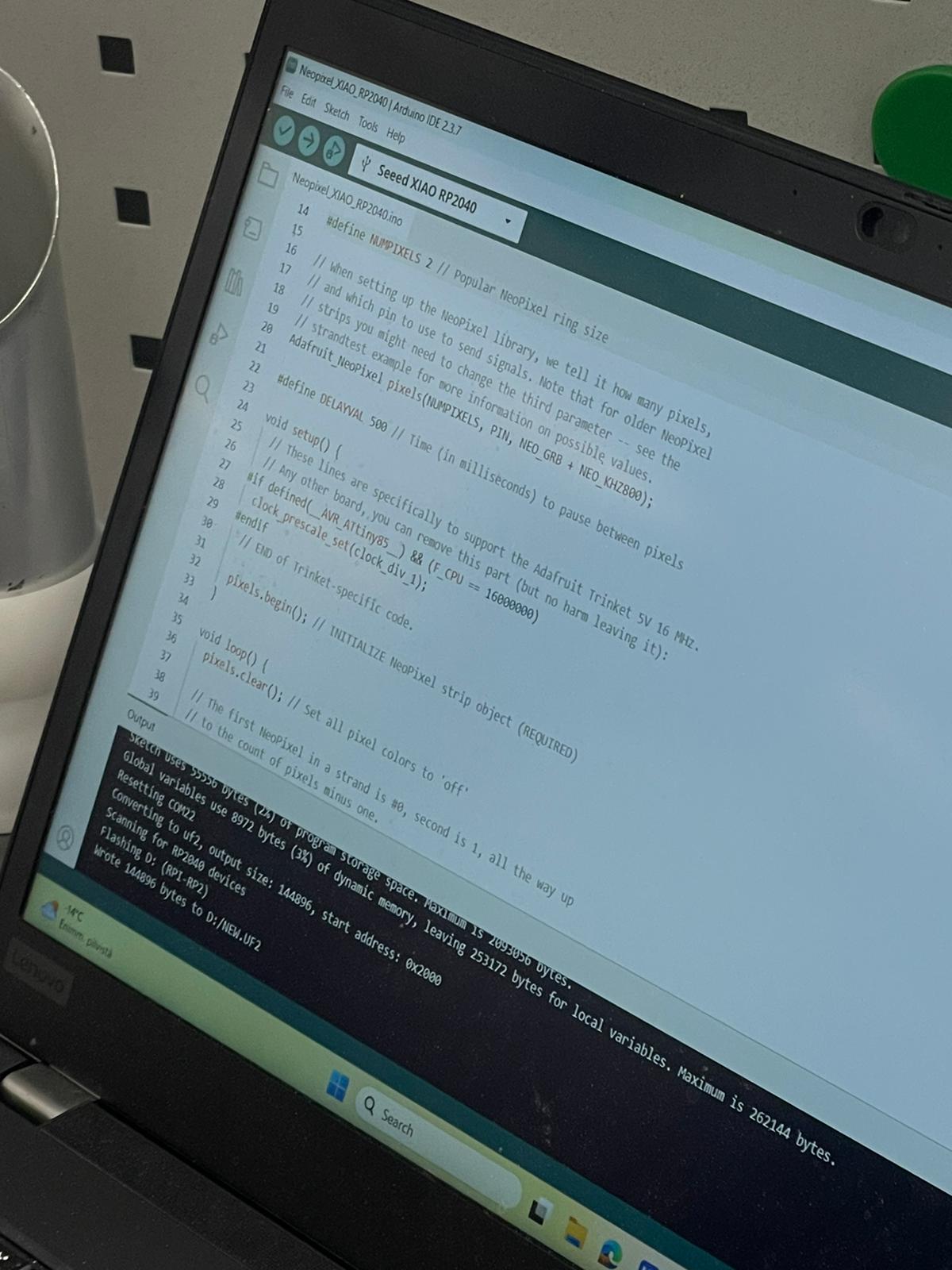
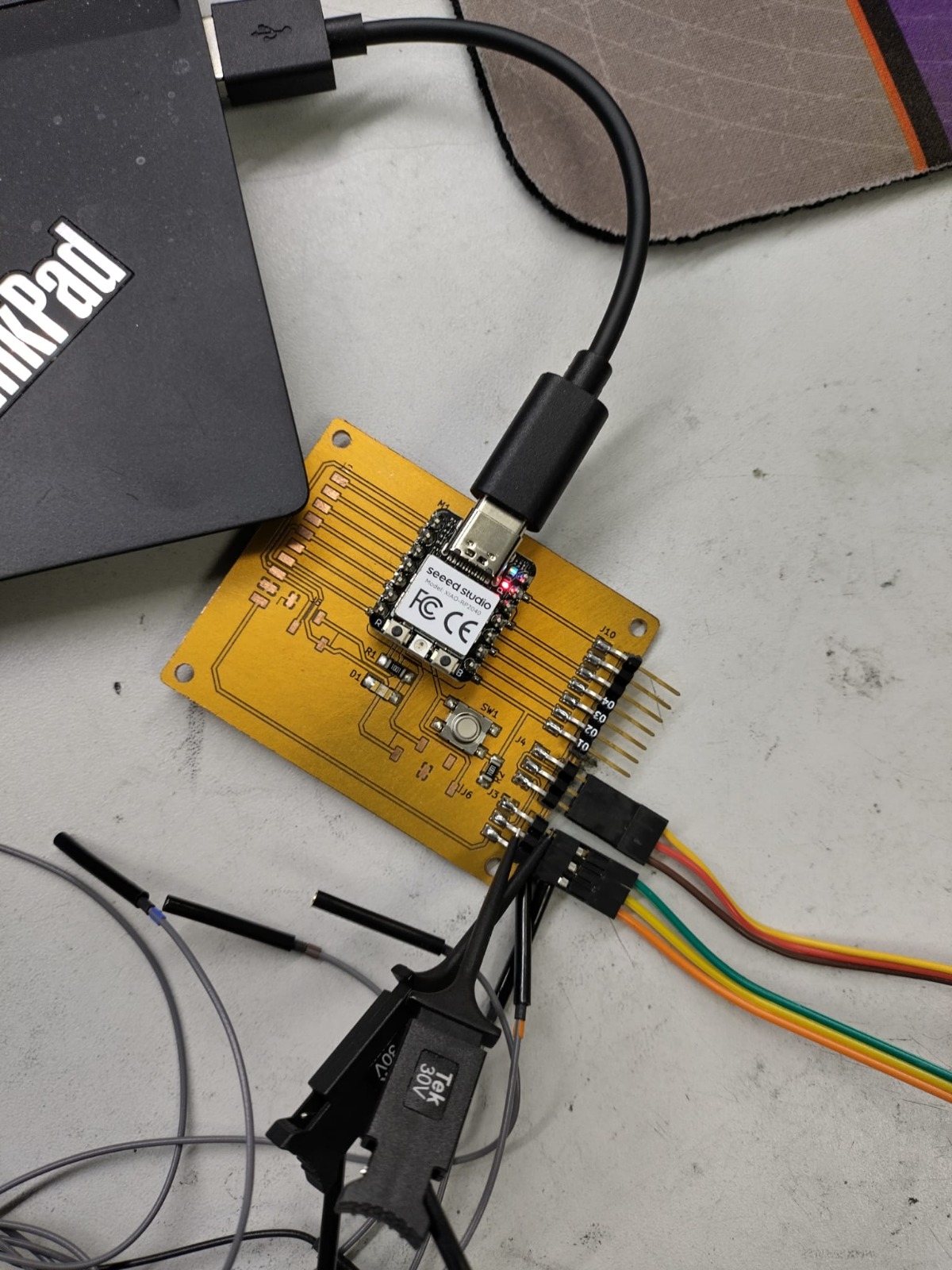
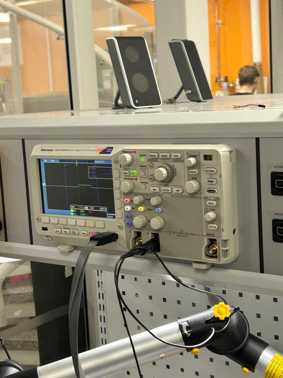
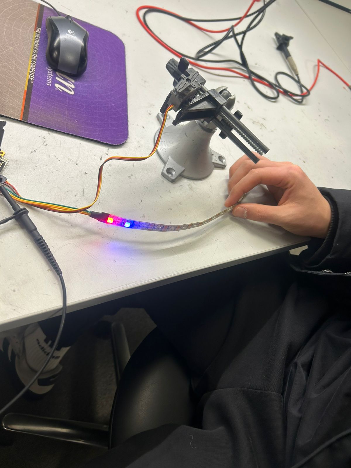
A PCB (with XIAO-RP2040 microcontroller) was connected to a laptop with a USB-A to USB-C connector. The connection provides power to the PCB/servomotor/neopixel and allows for programming of the microcontroller.
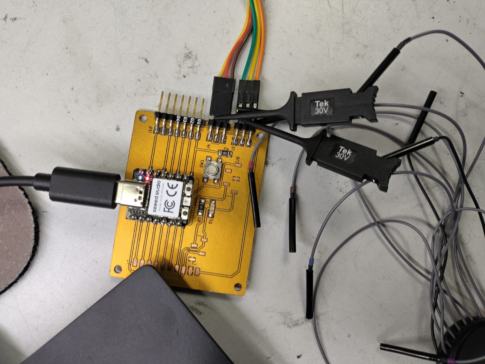
The Tek 30V Oscilloscope probe test hooks connected the Tektronix MSO 2002B Mixed Signal Oscilloscope to the PCB. Of the two Tek 30V Oscilloscope probe test hooks, one connects to ground, the other to signal. The cable of the ground test hook is coloured black whilst the cable of the signal test hook is coloured grey. Throughout both tests the ground test hook was connected to the ground wire of the neopixel (green).
Neopixel Test
For the neopixel test the signal test hook was connected to the signal output of the neopixel (yellow wire, neopixel). The Oscilloscope was monitored.
Servomotor Test
For the servomotor test the signal test hook was connected to the signal output of the servo-motor (yellow wire, servomotor). The Oscilloscope was monitored.
2. How Data Shows on the Oscilloscope
Servo Signal (PWM)
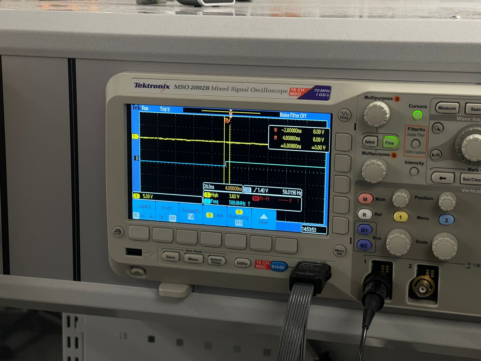
On your oscilloscope, the servo signal is represented by a consistent, repeating square wave.
- The "Heartbeat": It typically operates at 50Hz, meaning one pulse is sent every 20ms.
- Visualizing Position: You can see the position represented by the Pulse Width. A pulse lasting 1ms might represent one end of the servo's range (e.g., 0°), while 2ms represents the other (e.g., 180°).
- The Capture: In your oscilloscope images, you can see a clear "High" state followed by a long "Low" state, which is the classic signature of Pulse Width Modulation.
Neopixel Signal (High-Speed Serial)
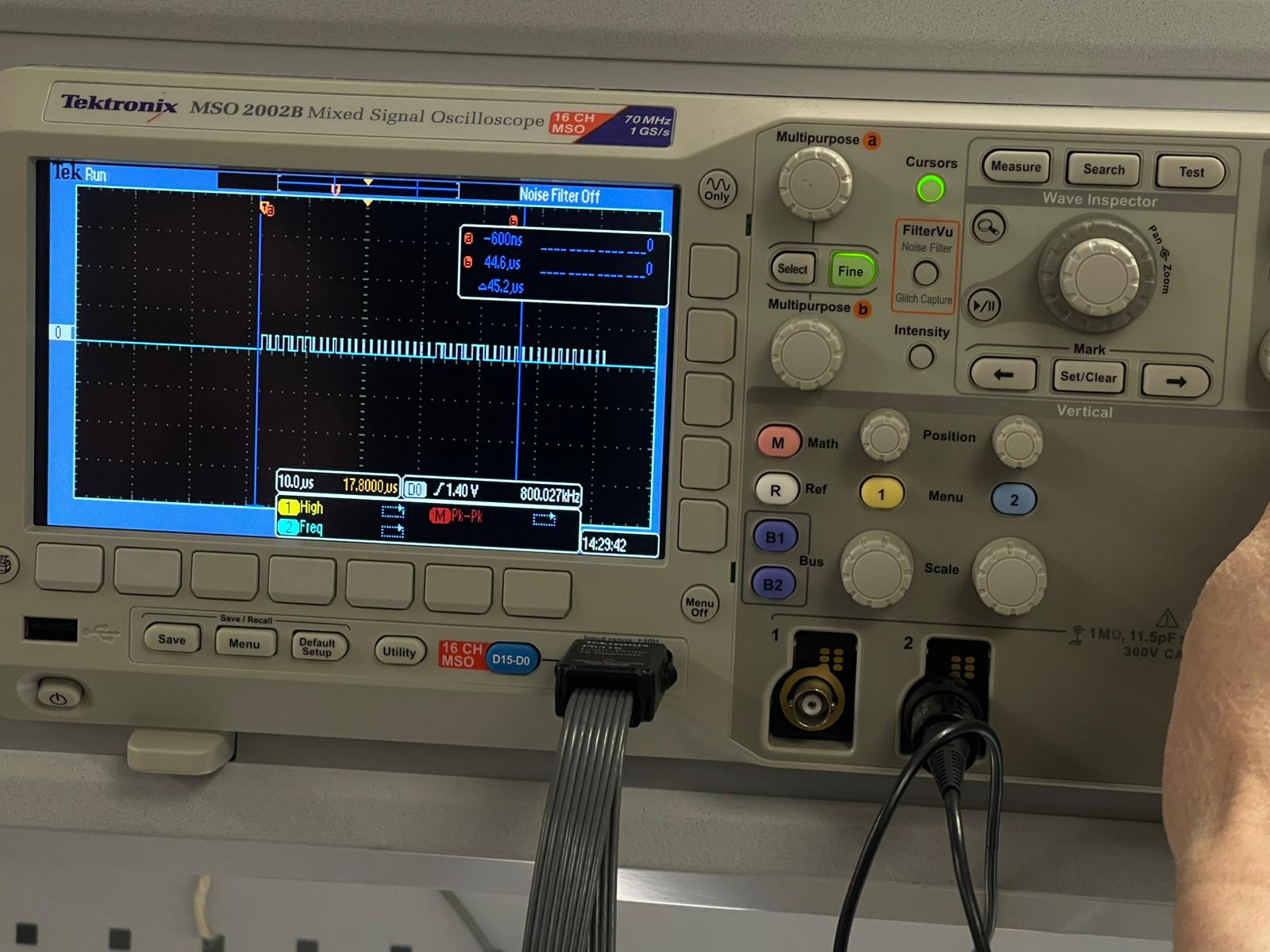
The Neopixel data looks very different; it appears as a dense, high-frequency "burst" of pulses.
- Speed: Unlike the slow 50Hz servo, Neopixels typically run at 800kHz.
- Digital Nature: The oscilloscope reveals the "analog nature" of these digital signals—specifically the Rise Time. Even though we see a square wave, it takes a tiny fraction of time (about 6 nanoseconds in your video) to transition from logic 0 to logic 1.
- The Capture: Your capture shows a series of varied-width pulses closely packed together, representing the binary data stream being sent to the LEDs.
The Special Rules of Neopixel Data
Neopixels (like the WS2812B) do not use a standard clock wire. Instead, they follow these specific data rules:
The "Color Sequence" Rule
While we often think in RGB, most Neopixels actually use a GRB (Green-Red-Blue) data order:
- Green: 8 bits (values 0-255)
- Red: 8 bits (values 0-255)
- Blue: 8 bits (values 0-255) This totals 24 bits of data for every single LED in the chain.
The "Pulse Shape" Rule
The LED determines if a bit is a 0 or a 1 by measuring the duration of the "High" part of the pulse, not just its existence:
- Logical 0: A very short "High" followed by a long "Low."
- Logical 1: A long "High" followed by a short "Low."
The "Self-Sorting" Chain Rule
This is the "special rule" of how the data flows through the strip:
- Data Consumption: The first Neopixel in the strand (index #0) "eats" the first 24 bits of data it hears.
- Data Passing: It then passes all remaining data in the stream to the next pixel.
- The Reset: After all data is sent, the microcontroller holds the line "Low" for a specific period (usually 50 microseconds). This is the Reset Signal that tells all pixels to simultaneously display their new colors.