title: Group Krajewski Hoa others summary: Group assignment for Interface and Application Programming week show_authors: true authors: - name: Miglio Krajewski email: Miglio.Krajweski@student.oulu.fi - name: Lý Thái Hoà email: Hoa.Ly@student.oulu.fi - name: Hadi Rezaeikarjani email: Hadi.Rezaeikarjani@student.oulu.fi
Walkthroughs
Each group member selected one walkthrough and documented their work.
BLE Walkthrough - XIAO ESP32C3
After reading through the instruction, the Seeed-RP2040 development board was replaced with an ESP32-C3 development board on the PCB. In arduino, the esp32 framework by espressif was installed in the boards manager. Then the library NimBLE-Arduino was installed. The ble.ino sketch was copied into the Arduino IDE and flashed to the ESP32-C3.
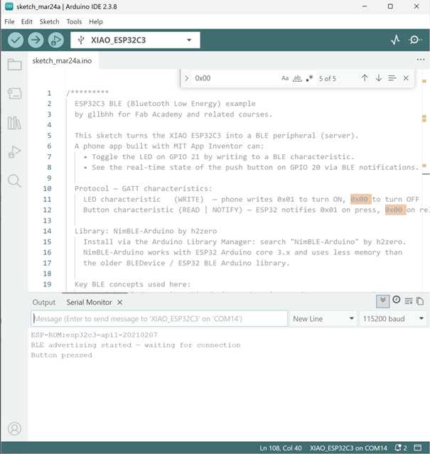
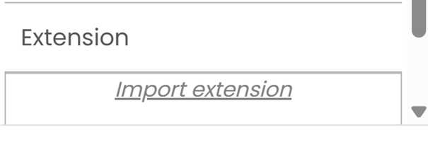
Subsequently, an application was built with the MIT APP INVENTOR. In order to build an appliation capable of communicating via bluetooth, a bluetooth extension had to be imported.

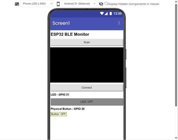
Then the interface was designed. The design tree (see the app inventor referenced above) is as follows:
´´´ Screen1 ├── Label — Text: "ESP32 BLE Monitor" FontSize: 20 Bold ├── Button (btnScan) — Text: "Scan" Width: Fill parent ├── ListView (listDevices) — Width: Fill parent, Height: 150px ├── Button (btnConnect) — Text: "Connect" Width: Fill parent Enabled: false ├── Label — Text: "LED — GPIO 21" Bold ├── Button (btnLed) — Text: "LED: OFF" Width: Fill parent BackgroundColor: Dark Gray Enabled: false ├── Label — Text: "Physical Button — GPIO 20" Bold ├── Label (lblButton) — Text: "Button: OFF" TextAlignment: Center └── BluetoothLE1 (non-visible — drag from Extensions palette) ´´´
The finished interface appears as follows:
After designing the interface, the logic was added.
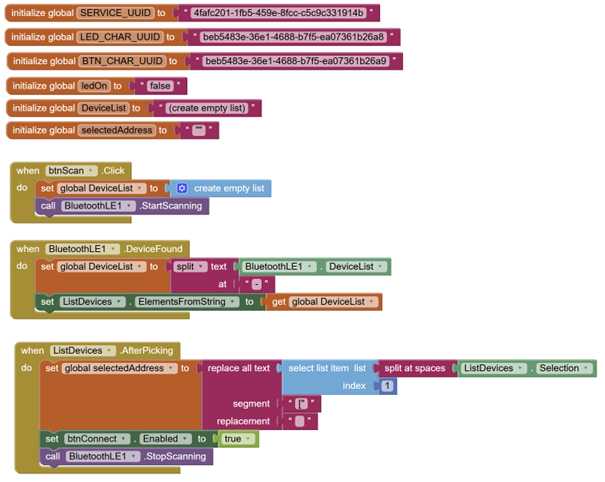
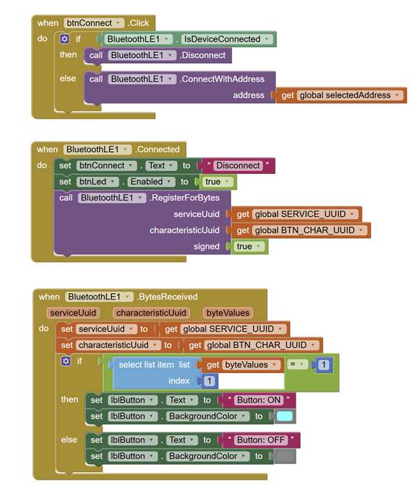
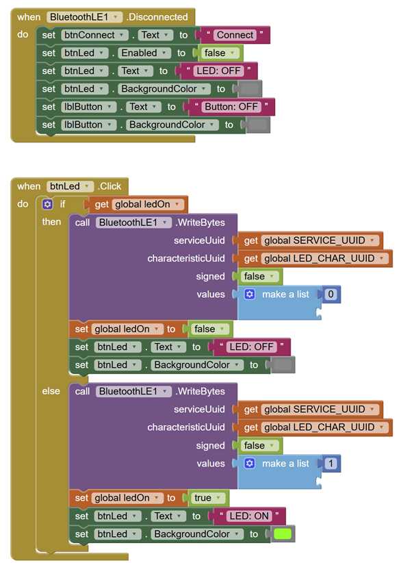
Although the application can be packaged as an .apk file and installed on an android device, there is also the possibility to stream the application to an android device for test purposes. In order to simplify the process, this was done. The MIT AI2 companion application was downloaded on my personal android device and used to stream the application. Testing the application was successful. The application scanned for bluetooth, connected to the ESP32-C3 via bluetooth and the LED lit up when the respective buttons in the interface were pushed.
Lightbub Toggle - Arduino + Processing Part 1
Step 1
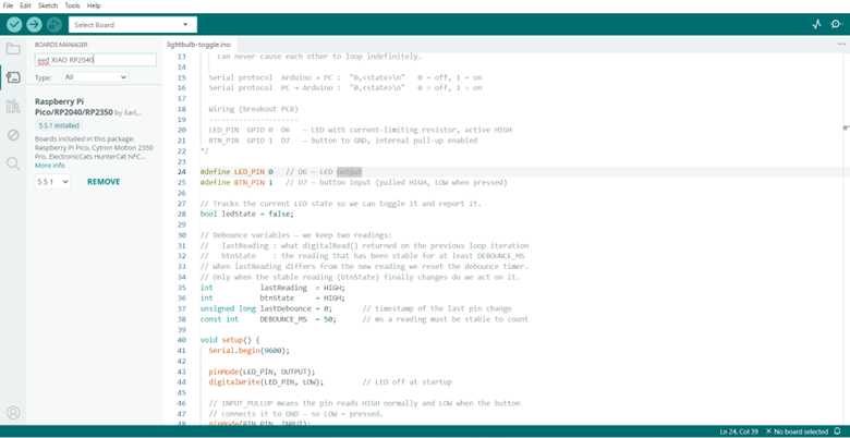
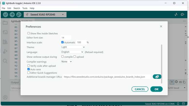
After choosing the Lightbulb Toggle - Arduino + Processing walkthrough, the Seeed XIAO RP2040 was installed using the boards manager: 1. Find the field "Additional boards manager URLs" and paste this URL into it: https://files.seeedstudio.com/arduino/package_seeeduino_boards_index.json 2. Click OK. 3. Go to Tools → Board → Boards Manager. 4. Search for "Seeed XIAO RP2040" and click Install. 5. Wait for the installation to finish, then close the Boards Manager.
Step 2
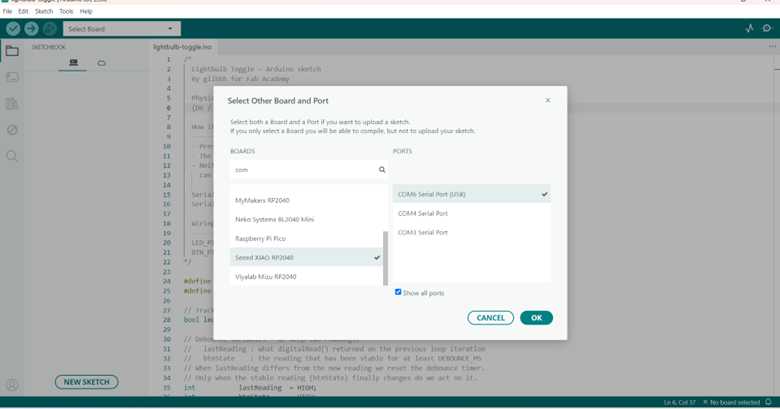
Following the steps in the guide, I tried to connect the board to the IDE. In the beginning, only com4 and com3 were shown, but when I connect my board, then UF2 gate appeared and I was able to select the UF2 board. However, the board did not connect. I asked Gleb for help and he suggested to press the D7 button and the restart button. After doing this the com6 gate appeared and I selected it. Finally, the board connected.
Step 3
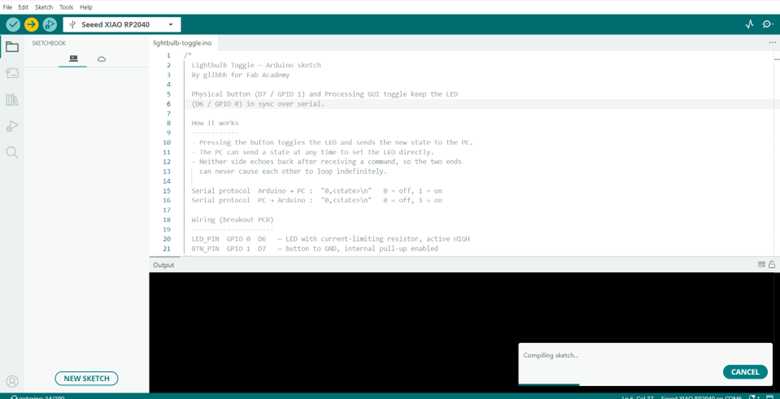
- After opening the example in the IDE, I clicked the Upload button (the arrow icon, or press Ctrl+U / Cmd+U).
- The IDE will compile the code and send it to the board. The progress bar at the bottom will show "Done uploading" when it finishes. The image demonstrates the process.
Step 4
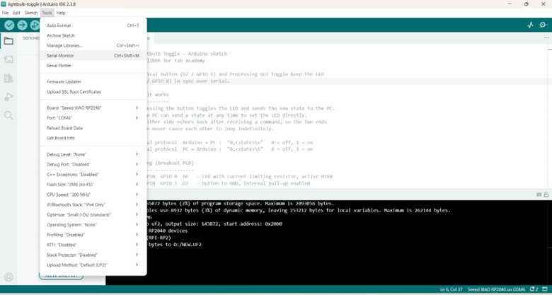
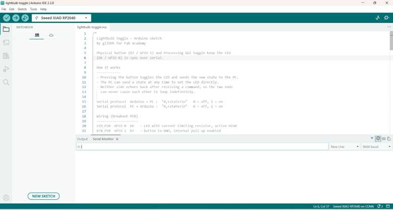
- Go to Tools → Serial Monitor.
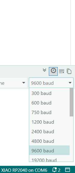
- Set the baud rate in the bottom-right corner to 9600.
- Press the physical button on the board (D7). The LED should toggle and you should see a message like 0,1 or 0,0 appear in the Serial Monitor.
- Close the Serial Monitor before running Processing — only one program can use the serial port at a time
Step 5
- Press the physical button on the board (D7). The LED should toggle and you should see a message like 0,1 or 0,0 appear in the Serial Monitor.
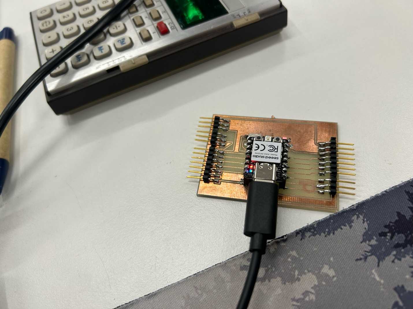
- When the button is not pressed, the voltage betteen button and ground is 0. When it is pressed, it goes to 3.3 volts. For default code in fab lab, it is opposite. In my case I just use input so it can change the state to another state not to pullup.
Lightbub Toggle - Arduino + Processing Part 2
Step 1
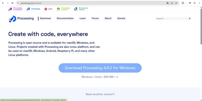
- Go to processing.org/download and download the version for your operating system.
- Unzip the downloaded archive and run the Processing application inside it. No installer is needed.
Step 2
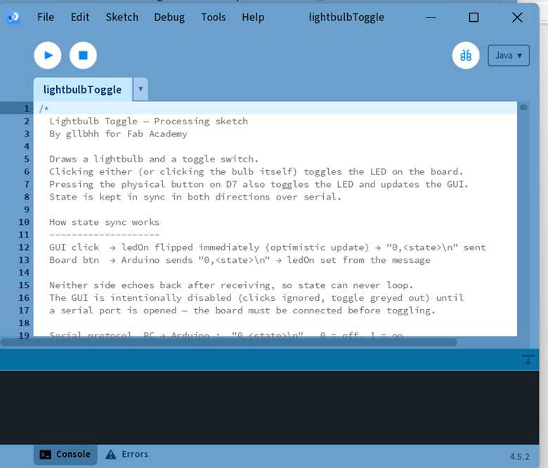
- Open the sketch
Step 3
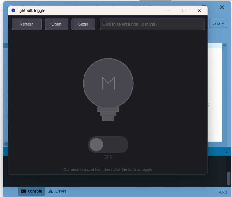
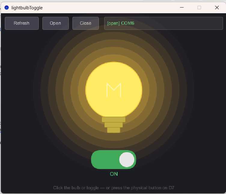
Click the Run button (the triangle/play icon, or press Ctrl+R / Cmd+R). A dark window will appear with a lightbulb, a toggle switch, and a row of buttons at the top.
Step 4
- The GUI starts disconnected. You need to tell it which serial port the board is on. Click Refresh to scan for available ports. The port selector box (the wide area to the right of the buttons) will update.
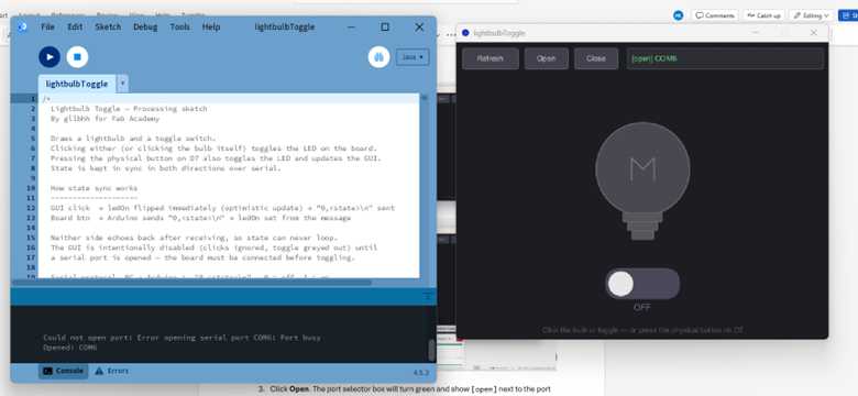
- Click the port selector box to cycle through the available ports until you see the one that corresponds to your board (same port name you used in Arduino IDE). In my case it is port com6. In my case I had not closed the arduino IDE and could not connect the com6. After closing it, it worked!
- Click Open. The port selector box will turn green and show [open] next to the port name. Tip: If you opened the Arduino Serial Monitor earlier, make sure you closed it. Only one program can use the serial port at a time — if it is busy, the Open button will not connect.
Step 5
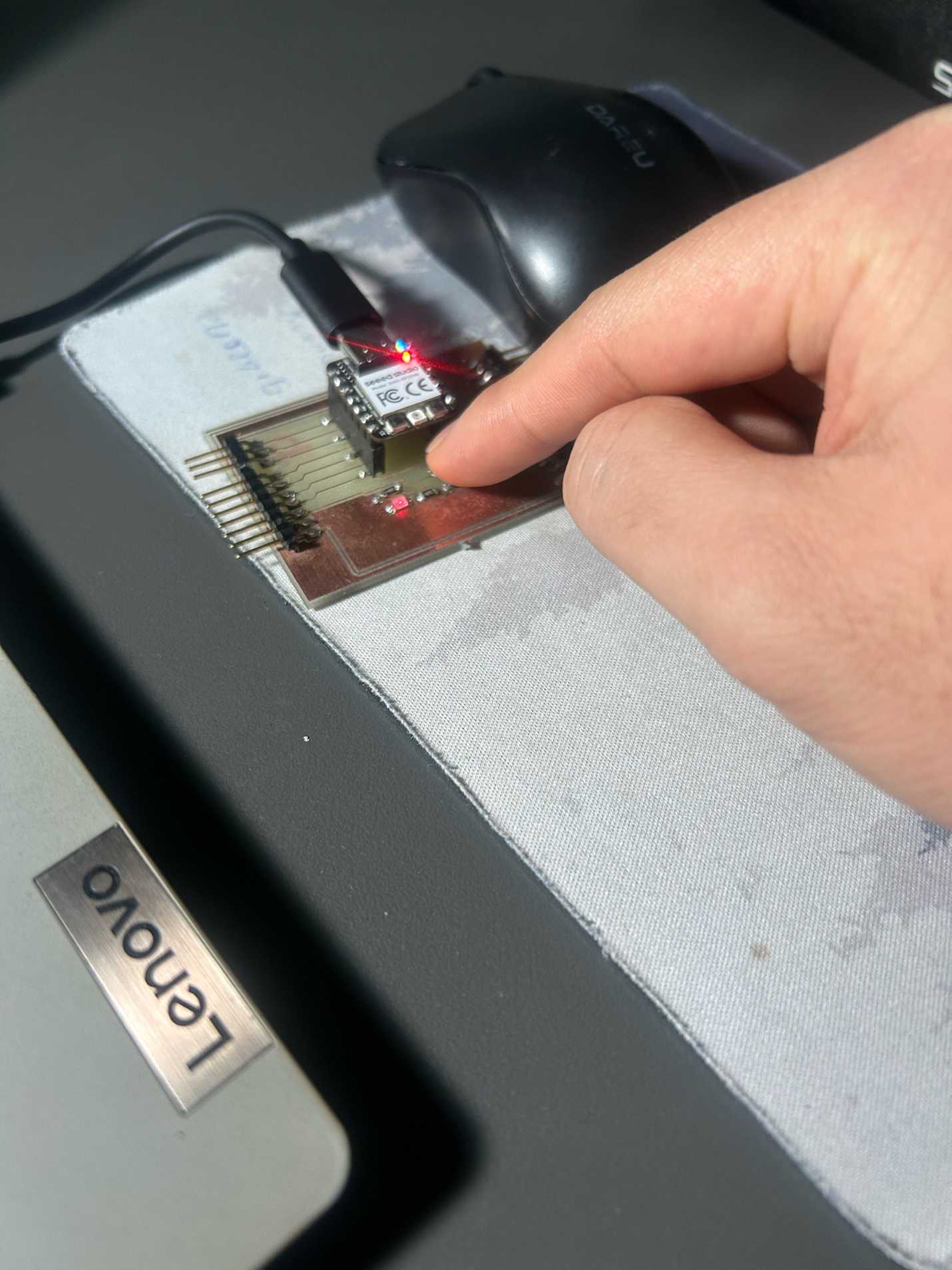
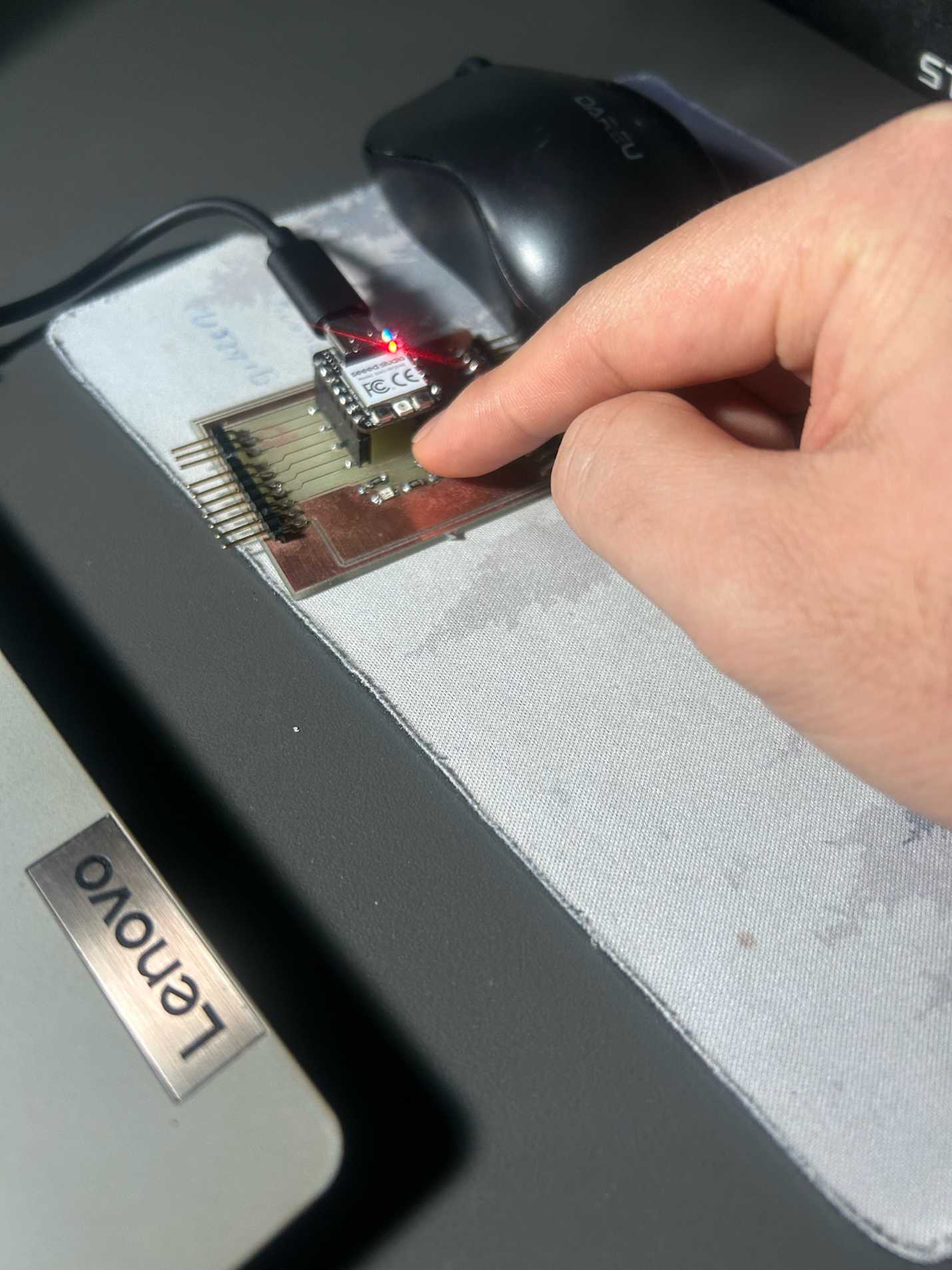
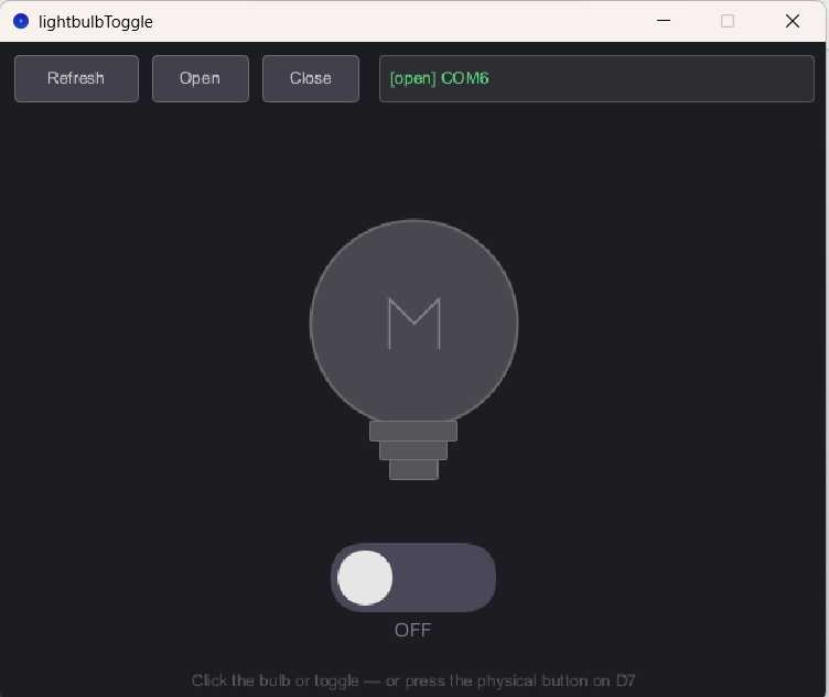
- Click the lightbulb or click the toggle switch to turn the LED on or off. when I switched the toogle switch . It turned on the real LED and also the lightbulb on the web . The same happenned when I turned it off. It worked the same when I turned the physical button .
- Press the physical button on the board (D7) to toggle from kthe hardware side. The GUI will update automatically.
QPad Processing
This week’s assignment focused on interfacing an application with hardware using the QPad board and Seeed Xiao RP2040. I used the example Arduino code named serial-display-debounced.ino from the Fab Lab Oulu repository: Link: https://gitlab.com/fab-lab-oulu/qpad-xiao-examples/-/blob/main/code-examples/arduino/serial-display-debounced/serial-display-debounced.ino This code demonstrates bidirectional communication between the computer and the QPad: • Touching the capacitive pads on the QPad sends debounced signals to the Arduino IDE Serial Monitor. • Text typed in the Serial Monitor is displayed on the QPad’s small OLED screen.
Hardware
• Seeed Studio XIAO RP2040 microcontroller • QPad board (with OLED display and 6 capacitive touch pads) • USB-C connection to laptop running Arduino IDE
Steps
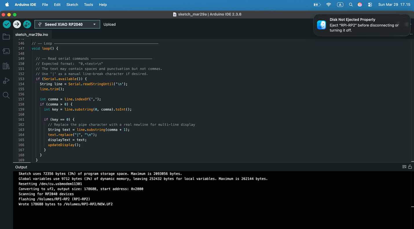
- Booting/Uploading the code to the Seeed Xiao RP2040 with QPad. Photo of the QPad connected to the laptop while uploading or booting the code
- QPad device when the device is ready to type in Serial Monitor. Photo showing the QPad powered on and ready, with Serial Monitor open on the laptop].
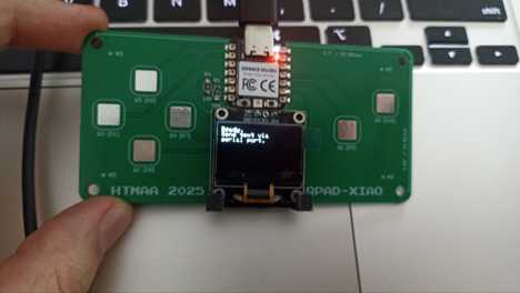
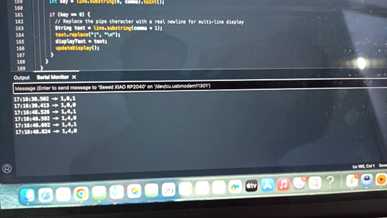
- Touching the Q Pad and output shown in Arduino IDE Serial Monitor. Photo of finger touching a QPad pad with the corresponding message visible in the Serial Monitor.
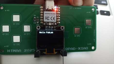
- Typing “Hello FabLab” in Serial Monitor and result shown on QPad monitor. Photo showing the text “Hello FabLab” typed in Serial Monitor and displayed on the QPad OLED screen.