Group1_nam
Group members
- Nam Nguyen
- Labeeb Zafar
- Siavash
- Nguyen Dinh
Electronic Design Week
Set up
1. Tools:
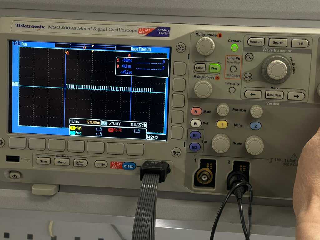
We used : - Signal oscilloscope - 2 probes for oscilloscope - PCB - USB-A to USB-C connector - Neopixel - Servomotor - Laptop
2. Before measuring:
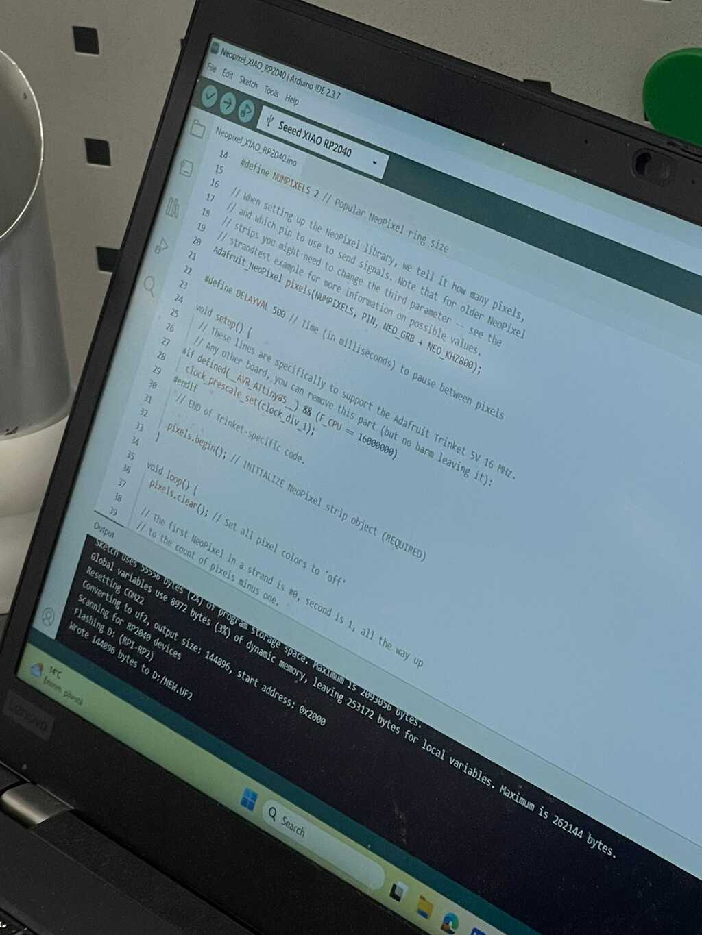
I connected the PCB and the laptop using USB-C to USB-A cable. Also, I made sure that I had a code for neopixel and servomotor. I flashed it into the microcontroller.
I turned on the oscilloscope and start measuring. The black probe was connected to the ground and the red probe was connected to the signal line.
Measurement
1. Servo motor
I placed the test hook to the yellow wire of the servo motor to get the signal.
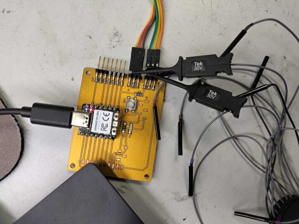
The output signal is a PWM signal. The longer the pulse width, the more the servo motor rotates.
2. Neopixel
I also placed the test hook to the yellow wire of the neopixel to get the signal.
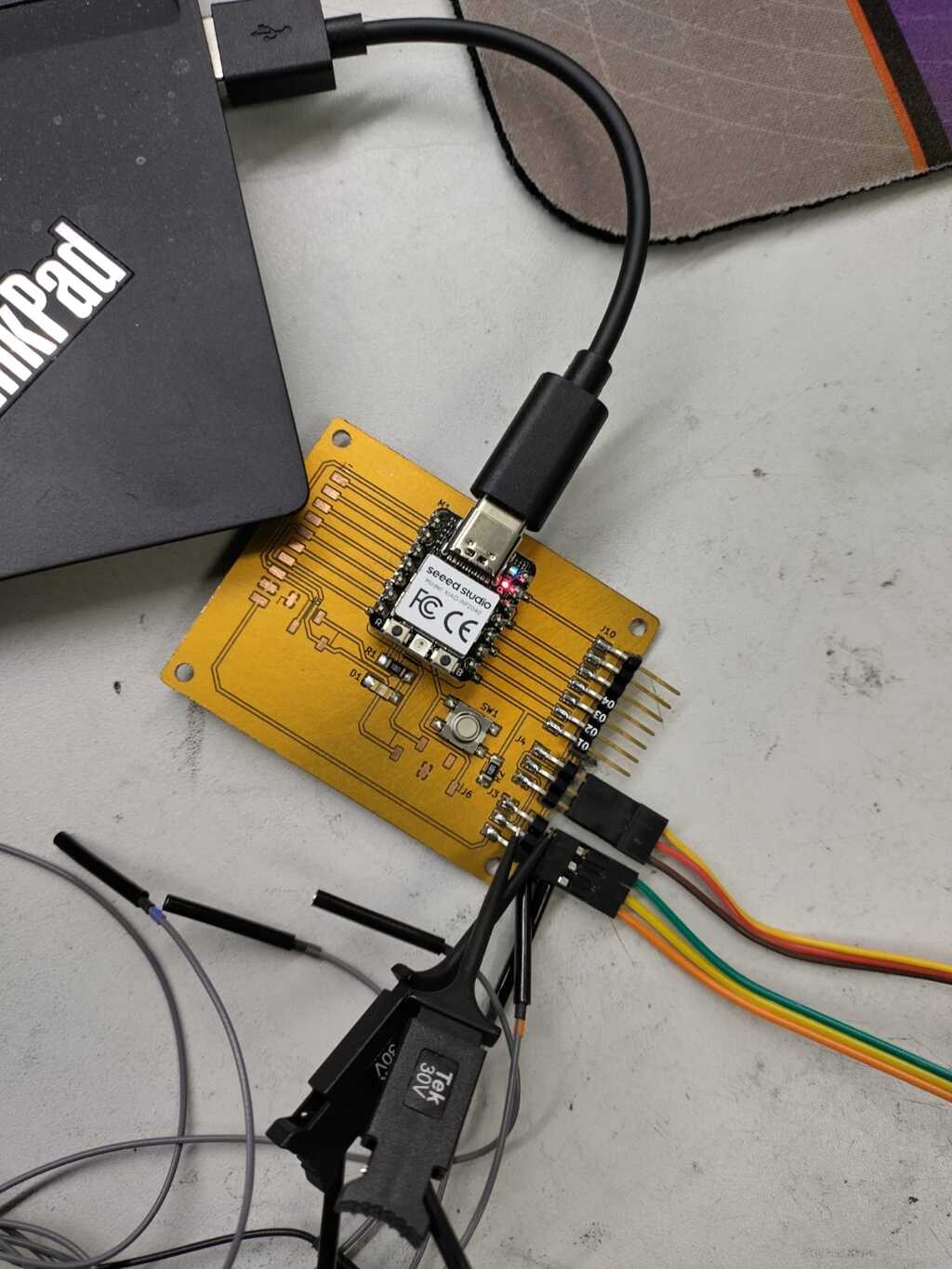 The output signal looks like an array of pulses which we think is the package of data which is sent in 1 moment.